Zero governor A -Z
----
Features
Specifications
Dimensions
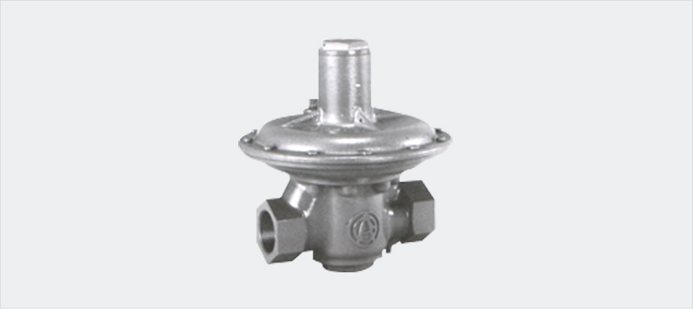
Features
– Zero governors maintain the gas pressure in the secondary side at around the atmospheric pressure regardless of changes in pressure and flow rate in the primary side.
– Available in a variety of models including a general use type (Type 1), high performance type (Type 2) and high capacity type (Type 11).
– For controlling the anticipated proportional mixing method.
– Some models can be used as a relief valve (safety valve).
Specifications
Standard specifications
Specifications for zero governor method
| Maximum primary working pressure (P1) | ※120kPa |
|---|---|
| Minimum primary working pressure (P2) | 0.5kPa |
| Range of secondary pressure (P2) adjustable by the spring |
Type 1-0.4 to 0kPa |
| Type 2・11-0.05 to +0.05kPa |
* 1. Models A8, 10, and 13Z-1 are 10 kPa. (Operating temperature is 0 to 60 °C.)
Specifications for pressure equalizing valve method
| Maximum primary working pressure (P1) | 50kPa |
|---|---|
| Maximum secondary working pressure (P2) | 30kPa |
| Maximum working differential pressure (P1-P2) | 30kPa |
| Spring-set pressure | -0.05 to +0.05kPa |
Note) 1 kPa = 101. 972 mmH2O (Operating temperature is 0 to 60 °C.)
Capacity (A8Z-1 to A50Z-1)
| Model | A8Z-1 | A10Z-1 | A13Z-1 | A20Z-1 | A25・30Z-1 | A40Z-1 | A50Z-1 | |
|---|---|---|---|---|---|---|---|---|
| Capacity factor (K) | — | — | 0.56 | 0.88 | 1.32 | 1.54 | 4.43 | |
| Differential pressure (P1-P2) kPa | 0.5 | 1.7 | 2.8 | 4 | 6 | 9 | 11 | 31 |
| 1 | 2.5 | 4 | 6 | 9 | 13 | 16 | 45 | |
| 2.5 | 3 | 5 | 9 | 14 | 21 | 25 | 70 | |
| 5 | 3 | 5 | 13 | 20 | 30 | 35 | 100 | |
| 10 | 3 | 5 | 18 | 28 | 42 | 49 | 141 | |
| 15 | — | — | — | 35 | 52 | 60 | 172 | |
| 20 | — | — | — | 40 | 60 | 70 | 199 | |
Capacity (A20Z-2 to A75Z-1)
| Model | A20Z-2 | A25・30Z-2 | A40Z-2 | A50Z-2 | A40Z-11 | A50Z-11 | A75Z-11 | |
|---|---|---|---|---|---|---|---|---|
| Capacity factor (K) | 0.85 | 1.54 | 1.85 | 5.31 | 6.44 | 9.90 | 22.9 | |
| Differential pressure (P1-P2) kPa | 0.5 | 6 | 11 | 13 | 38 | 46 | 70 | 163 |
| 1 | 9 | 16 | 19 | 53 | 65 | 100 | 231 | |
| 2.5 | 13 | 25 | 30 | 85 | 102 | 157 | 365 | |
| 5 | 19 | 35 | 42 | 119 | 145 | 223 | 516 | |
| 10 | 27 | 49 | 59 | 169 | 205 | 315 | 730 | |
| 15 | 33 | 60 | 73 | 207 | 250 | 385 | 895 | |
| 20 | 38 | 70 | 84 | 239 | 289 | 445 | 1033 | |
Dimensions
Dimensions(A8Z-1 to A50Z-1)
| Model | A8Z-1 | A10Z-1 | A13Z-1 | A20Z-1 | A25Z-1 | A30Z-1 | A40Z-1 | A50Z-1 |
|---|---|---|---|---|---|---|---|---|
| A(mm) | 50 | 60 | 74 | 112 | 140 | 140 | 140 | 220 |
| B(mm) | 74 | 78 | 108 | 105 | 141 | 142 | 144 | 221 |
| C(mm) | 16 | 20 | 21 | 25 | 27 | 28 | 30 | 51 |
| D(mm) | □73 | □73 | φ116 | φ116 | φ169 | φ169 | φ169 | φ246 |
| E | Rc1/4 | Rc3/8 | Rc1/2 | Rc3/4 | Rc1 | Rc11/4 | Rc11/2 | Rc2 |
| Mass(kg) | 0.2 | 0.2 | 1.0 | 0.7 | 1.3 | 1.4 | 1.4 | 9.3 |
Dimensions(A20Z-2 to A75Z-11)
| Model | A20Z-2 | A25Z-2 | A30Z-2 | A40Z-2 | A50Z-2 | A40Z-11 | A50Z-11 | A75Z-11 |
|---|---|---|---|---|---|---|---|---|
| A(mm) | 112 | 140 | 140 | 140 | 220 | 200 | 250 | 340 |
| B(mm) | 135 | 200 | 201 | 203 | 281 | 262 | 318 | 646 |
| C(mm) | 25 | 27 | 28 | 30 | 51 | 53 | 64 | 120 |
| D(mm) | φ169 | φ246 | φ246 | φ246 | φ330 | φ246 | φ330 | φ450 |
| E | Rc3/4 | Rc1 | Rc11/4 | Rc11/2 | Rc2 | Rc11/2 | Rc2 | JIS 5K3B Flange |
| Mass(kg) | 1.5 | 5.5 | 5.5 | 5.5 | 15.0 | 7.0 | 18.0 | 55.0 |
・Specifications are subject to change without notice.
・Product Warranties