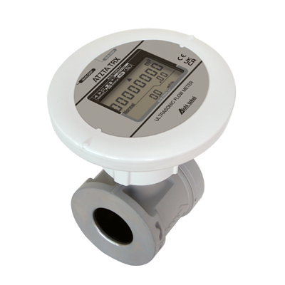
Electromagnetic types
Instantaneous display
Straight pipe section unnecessary
Cooling water measurement
No moving parts
- Top
- Product Information
- Flow Sensors
Flow Sensors
Flow Sensors
- Search for another product
Search by Category
Search by Product Support Category
Search by Market
Search by Model or Product Name
*Include a space between the model number and the nominal diameter. (e.g.: SU 50)
- Filter by measurement principle
- Filter by liquid type
Electromagnetic types
Capacitive Electromagnetic Flow Sensor(FMO)
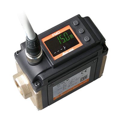
A flow rate monitor for FA that is resistant to Foreign substance and deposits and can be installed in a small space. Stable quality can be achieved by monitoring cooling water for mold molding, die casting machines, and injection molding machines, as well as coolant fluid monitoring for cutting machines.
Small Electromagnetic Flow Sensor
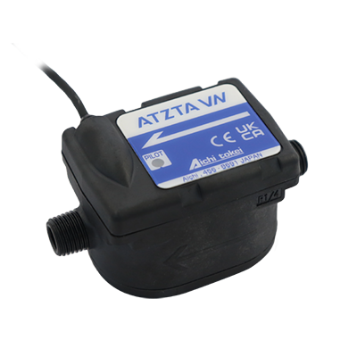
Electromagnetic
Straight pipe section unnecessary
No moving parts
- Model:
- ATZTA VN
- Nominal diameter:
- 5mm(R1/4)・10mm(R1/2)・20mm(R1)
- Standards certification:
- RoHS、CE、UKCA
Model VN is the cost-saving electromagnetic flow sensor that is compact and does not require any straight pipe length so that it can be easily built in the machines and devices. Due to its excellent small flow-rate measurement and repeatability, it has merits in various applications such as pesticide spraying agricultural drone, milk feeding machine for calves, medical cleaning equipment, Foam (CAFS) type firefighting vehicle, remaining amount management of beer server’s tank, 3D metal printer, etc.
Small Electromagnetic Flow Sensors
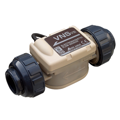
Electromagnetic types
Chemical liquid measurement
Pulsation measurement
No moving parts
- Model:
- VNS
- Nominal diameter:
- 5mm/10mm (socket type union joint 16A) ・20mm (socket type union joint 20A)
- Standards certification:
- RoHS、CE、UKCA
Model VNS is the electromagnetic flow sensor that is compact and does not require any straight pipe length so that it can be easily built in the machines and systems. Chemical solutions including sodium hypochlorite, caustic soda, etc., can be measured. Due to its excellent small flow-rate measurement and repeatability, it has merits in various applications such as water purification plant, distribution reservoir, sterilization system, factory’s wastewater treatment, etc.
Vane Wheel types
Flow Sensor
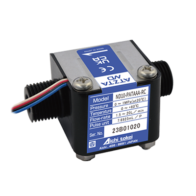
Vane Wheel types
Long seller
- Model:
- ATZTA ND
- Nominal diameter:
- 5mm・10mm(R1/2)・ 20mm(R3/4)
- Standards certification:
- RoHS、CE
The ND-type flow sensor has the measuring principle of impellers and is suitable for measuring various types of liquid. It is one of our best-selling products with high quality at a low price.
Instantaneous Flow-rate/ Integrating Flow Volume Flowmeter

Vane Wheel types
No power supply required
Instantaneous integration display
- Model:
- NW / NW-P
- Nominal diameter:
- 5mm・10mm(R1/2)・ 20mm(R3/4)
- Standards certification:
- RoHS、CE
ND series offers high accuracy measurement of not only cold and warm water but also pure water, chemical fluids, etc. It is light-weighted compact body and is compatible with various kinds of fluids with the carefully selected casing materials such as PP, ETFE, PPO, etc., and with the highly sensitive magnetic sensor of our own development. This series is therefore widely applicable for various flow measurements and its control and monitoring as well. Model NW (Local display type) Model NW-P (With pulse output)
Oval gear types
Ovel gear Flow Sensor
Oval gear types
Oil measurement
Micro flow measurement
Long-selling
Model OF is the oval-gear flow sensor that is compact and does not require any straight pipe length so that it can be easily built in the machines and systems. Fluids including fuels such as kerosene and heavy oil can be measured. Due to its excellent repeatability, it has merits in various applications such as dialysis machine, offset rotary printing machine, electric oven, bread machine, Vending machine for household cleaner, Adblue refilling dispenser for diesel cars, etc.
Microstream Sensor
Ovel gear types
Oil measurement
No power supply required
Micro flow measurement
Instantaneous integration display
- Model:
- OF-WN / OF-WP
- Nominal diameter:
- 5mm(R1/4)・10mm(R1/2)
- Standards certification:
- RoHS、CE
High Cost-Performance The MICROSTREAM Sensor was developed to meet the fluid engineering demands for a precise, easy-to-use flow-rate control and monitoring system that can be applied to a wide range of fields. This is a type of minute flow sensor OF-WN with display. Flow meter with optional pulse output.
Turbine types
Small-size Flow Sensor
Turbine types
Compact
Long seller
Model NDV10 is a simple type flowsensor with high quality and low price, which are to make the product become much easier to be adopted by you. Installing the flowsensor in devices developed by you or systems will help improve their functionality such as control and monitoring of the flow.
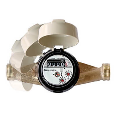
Water
Capacitive Electromagnetic Flow Sensor(FMO)
Electromagnetic types
Instantaneous display
Straight pipe section unnecessary
Cooling water measurement
No moving parts
- Model:
- CX
- Nominal diameter:
- 10mm(Rc3/8)・15mm(Rc1/2)・20mm(Rc3/4)
- Standards certification:
- RoHS、CE、UKCA
A flow rate monitor for FA that is resistant to Foreign substance and deposits and can be installed in a small space. Stable quality can be achieved by monitoring cooling water for mold molding, die casting machines, and injection molding machines, as well as coolant fluid monitoring for cutting machines.
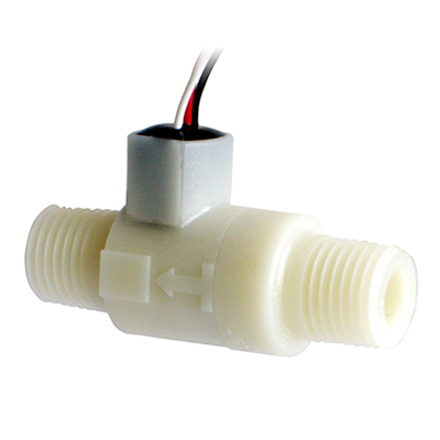
Small Electromagnetic Flow Sensor
Electromagnetic
Straight pipe section unnecessary
No moving parts
- Model:
- ATZTA VN
- Nominal diameter:
- 5mm(R1/4)・10mm(R1/2)・20mm(R1)
- Standards certification:
- RoHS、CE、UKCA
Model VN is the cost-saving electromagnetic flow sensor that is compact and does not require any straight pipe length so that it can be easily built in the machines and devices. Due to its excellent small flow-rate measurement and repeatability, it has merits in various applications such as pesticide spraying agricultural drone, milk feeding machine for calves, medical cleaning equipment, Foam (CAFS) type firefighting vehicle, remaining amount management of beer server’s tank, 3D metal printer, etc.
Flow Sensor
Vane Wheel types
Long seller
- Model:
- ATZTA ND
- Nominal diameter:
- 5mm・10mm(R1/2)・ 20mm(R3/4)
- Standards certification:
- RoHS、CE
The ND-type flow sensor has the measuring principle of impellers and is suitable for measuring various types of liquid. It is one of our best-selling products with high quality at a low price.
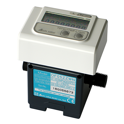
Instantaneous Flow-rate/ Integrating Flow Volume Flowmeter
Vane Wheel types
No power supply required
Instantaneous integration display
- Model:
- NW / NW-P
- Nominal diameter:
- 5mm・10mm(R1/2)・ 20mm(R3/4)
- Standards certification:
- RoHS、CE
ND series offers high accuracy measurement of not only cold and warm water but also pure water, chemical fluids, etc. It is light-weighted compact body and is compatible with various kinds of fluids with the carefully selected casing materials such as PP, ETFE, PPO, etc., and with the highly sensitive magnetic sensor of our own development. This series is therefore widely applicable for various flow measurements and its control and monitoring as well. Model NW (Local display type) Model NW-P (With pulse output)
Small-size Flow Sensor
Turbine types
Compact
Long seller
Model NDV10 is a simple type flowsensor with high quality and low price, which are to make the product become much easier to be adopted by you. Installing the flowsensor in devices developed by you or systems will help improve their functionality such as control and monitoring of the flow.
Chemical Liquid
Small Electromagnetic Flow Sensors
Electromagnetic types
Chemical liquid measurement
Pulsation measurement
No moving parts
- Model:
- VNS
- Nominal diameter:
- 5mm/10mm (socket type union joint 16A) ・20mm (socket type union joint 20A)
- Standards certification:
- RoHS、CE、UKCA
Model VNS is the electromagnetic flow sensor that is compact and does not require any straight pipe length so that it can be easily built in the machines and systems. Chemical solutions including sodium hypochlorite, caustic soda, etc., can be measured. Due to its excellent small flow-rate measurement and repeatability, it has merits in various applications such as water purification plant, distribution reservoir, sterilization system, factory’s wastewater treatment, etc.
Oil
Ovel gear Flow Sensor
Oval gear types
Oil measurement
Micro flow measurement
Long-selling
Model OF is the oval-gear flow sensor that is compact and does not require any straight pipe length so that it can be easily built in the machines and systems. Fluids including fuels such as kerosene and heavy oil can be measured. Due to its excellent repeatability, it has merits in various applications such as dialysis machine, offset rotary printing machine, electric oven, bread machine, Vending machine for household cleaner, Adblue refilling dispenser for diesel cars, etc.
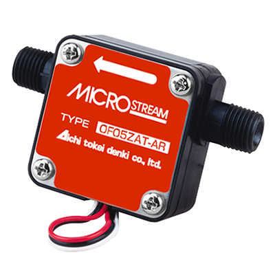
Microstream Sensor
Ovel gear types
Oil measurement
No power supply required
Micro flow measurement
Instantaneous integration display
- Model:
- OF-WN / OF-WP
- Nominal diameter:
- 5mm(R1/4)・10mm(R1/2)
- Standards certification:
- RoHS、CE
High Cost-Performance The MICROSTREAM Sensor was developed to meet the fluid engineering demands for a precise, easy-to-use flow-rate control and monitoring system that can be applied to a wide range of fields. This is a type of minute flow sensor OF-WN with display. Flow meter with optional pulse output.
CADデータご使用条件
CADデータをダウンロードされる前に、以下の条件を十分お読みください。
この条件についてご同意頂けない場合は、CADデータのダウンロードはお控えください。
ダウンロードされた場合は、このご利用条件につきご承諾頂いたものとさせて頂きます。
- このCADデータは弊社商品をお使い頂く製品の設計検討のみにご使用ください。
本データに基づく複製品の製作、およびその他上記使用目的以外の本件データの使用は厳禁とします。 - ダウンロードされたCADデータは、上記1の目的に使用後は全て消去してください。
- このCADデータは弊社商品の仕様を保証するものではありません。
このCADデータを使用したことによって生じた損害については、理由の如何に関らず補償は一切致しません。 - ダウンロードされたCADデータの図面要素から抽出される値については、実際の商品と一致することを保証するものではありません。
- 商品改良等のために、予告なしにCADデータの内容を変更する場合があります。
ダウンロードされたCADデータに対する内容変更のご連絡は一切致しませんのでご了承ください。 - 採用決定の際は、最寄りの愛知時計電機株式会社 支店営業所へ承認用の仕様書・図の請求をお願いします。
- CADデータは,中間フォーマット形式でのご提供になりますので、お客様でインポートされる際に、正常に読み込めない場合がございます。
Related Content
-

- Compliance Status of Flowmeters and Flow Sensors with Laws, Regulations, and Standards of Various Countries
- Compliance status of flow meters and flow sensors with laws and standards of various countries (RoHS, CE, UKCA).
-

- Initiatives and Track Records
- View the list of Initiatives and Track Records at Aichi Tokei Denki.
-
- Discontinued Products
- View the list of discontinued products at Aichi Tokei Denki.
-

- Support and Inquiries
- View the list of Support and Inquiries at Aichi Tokei Denki.